
Last Updated on 24 November 2021 by Motorsport
Tuned engines need careful monitoring to save expensive damage, or to get the maximum benefit from the modifications done. A production car dash will give basic information, but sometimes it is of the “whoops too late” variety, for instance the oil pressure warning light coming on after the damage is done. Tuned engines may also require a higher reading than the standard gauge.
There are many parameters that can be monitored with an appropriate gauge. The most common are oil pressure, water temperature, RPM, oil temperature, boost pressure, fuel level, fuel pressure, air / fuel ratio and battery voltage. Less common gauges are exhaust gas temperature, transmission temperature, brake bias, vacuum, even intercooler in and out temperature.
The four types of gauge
In motorsport there are four distinct types of gauges you can choose to get all your in-car information, these being:
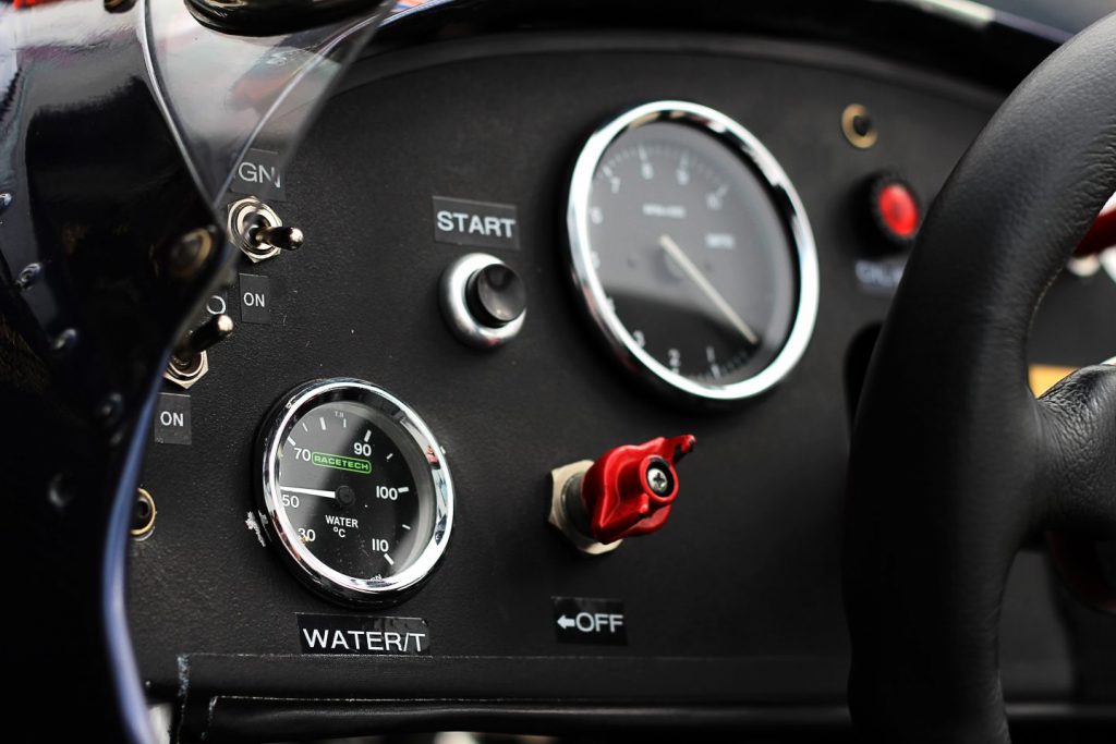
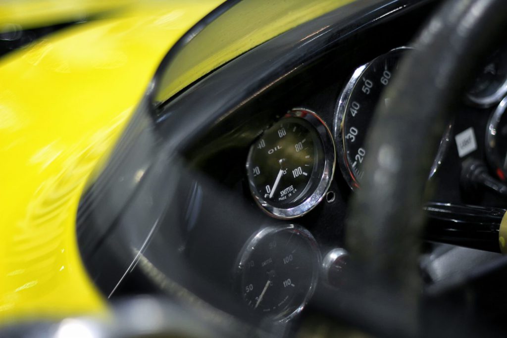
- Analogue – a gauge with pointer needle to figures on the face
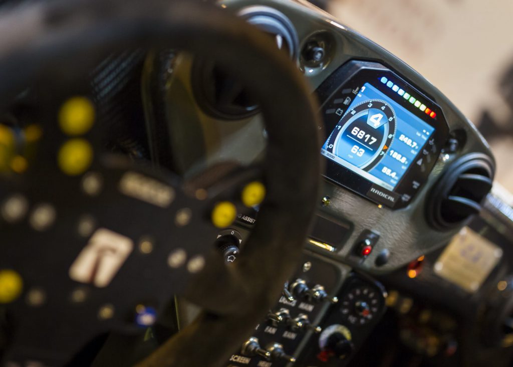
- Digital – LCD (liquid crystal display) figures read up or down on the face
- Dual Gauge – shows two figures at once can be analogue or digital or analogue / digital
- Dash display / Dash Logger – these are typically an analogue tachometer with a digital display for other parameters built into one neat compact unit. Some units are completely digital and many also feature built in warning lights. A dash display will show information live and a dash logger will do the same but keep the readings for future download.
Analogue gauges are available in a choice of two operation types depending on your requirements, as detailed below:
Mechanical
The sender is non-electrical and will read without any current feed. Temperature gauges usually feature a mercury filled pipe while pressure gauges use a capillary tube. These are easy to connect to the engine or component but have the disadvantage of the pipe or tube going directly into the gauge. This is not ideal if it is an oil or fuel pressure gauge, for obvious reasons! Generally, this is an appropriate choice for open cars without charging systems and minimal electrics.
Electrical
The sender converts the reading into an electrical signal for the gauge to read. Air core gauges are generally entry level and give a 90-degree needle sweep. The higher spec gauges are normally a stepper motor type that gives a 270-degree needle sweep which is more accurate and easier to read. The senders for electrical gauges are normally small, making them easy to fit on the engine or other components. The feed to the gauge is an electrical wire, providing a safer choice for going into the car interior.
Choosing Sensors and adaptors
Once the type of gauge is decided on, thought must be given to how the sensor, or sensors, will connect to the engine or component to be read.
Oil Pressure
The oil pressure reading is normally taken from the gallery where the low oil pressure switch is located. The most common option is to fit an oil pressure t-piece. This has a male thread facing the engine block to match the vehicle application. The rear of the t-piece will have a corresponding female thread to allow the oil switch to screw back in. The t-piece will have a side port (sometimes more than one). The side port is normally 1/8” NPTF or M10x1. This can be used with a male / male adaptor to take an oil pressure pipe if used with a mechanical gauge.
An electrical sensor can often be fitted in the t-piece. If the application has very little space or has an electrical sender which is bulky, a remote t piece kit can allow easy fitment.
Water temperature
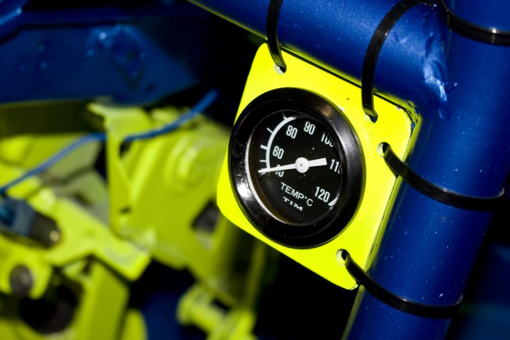
The water temperature sender can often be fitted in place of the factory unit with an appropriate adaptor if the thread is different, the thread of the existing sender will need determining in this case.
If there is no factory sender, it is hard to reach, or in some cases too corroded to risk removal, there are several options to allow the new sender to work. This can also be useful if you wish to run the original sender and gauge.
The first option is an inline hose adaptor. This is available in all common hose sizes and the sender screws in to measure the water flow. The adaptor fits into the water hose by cutting the hose and pushing it back on either side of the adaptor.
The second option if the radiator or header tank has a spare blanking plug is to use male to female adaptor for the two threads. The male thread matches the radiator with the female thread being the same as the sender being used.
Oil temperature
Installing an oil temperature gauge is more complicated than the above as most engines do not have a provision for measuring this parameter. There are a few options to consider.
If the engine has an oil cooler fitted, an adaptor can be fitted in the oil cooler hoses using an in-hose adaptor. There are also male to female threaded adaptors that can sandwich between the oil cooler take off plate thread and the oil line fitting thread.
The second option is fitting an adaptor into the sump plug, provided the thread is bigger than the sensor thread. This will require a male to female adaptor. If the thread is small or points towards the floor, a new hole can be tapped in the side of the sump or an appropriate adaptor welded in place.
The same adaptors can also be used in the oil tank if the car is running a dry sump system. If the engine has a remote oil filter head these are sometimes pre-tapped to take a sensor, either directly or with an adaptor (some production cars have a removeable blanking plug on the standard filter head which can be adapted the same way).
We have seen oil temperature senders fitted into the oil gallery as with oil pressure senders, via an oil t-piece. However, this tends to give the temperature of the adaptor rather than the oil due to the small flow of oil, so we do not recommend doing this. This method should only be used as a last resort if none of the above will work
Boost pressure
The boost pressure is measured between the turbo feed (or supercharger feed) and the cylinder head. The mechanical gauges will either have a push on pipe or a pipe with a threaded end.
These are normally fitted via a t piece into the wastegate pipe. They can also fit to other pipes that see intake manifold pressure. If the engine has an unused blanking plug on the pressure side this can be used with the appropriate threaded adaptor.
An electrical boost gauge will have a male threaded sensor. This will need to be fitted in an inline adaptor, or via a threaded adaptor if there are any blanking plugs that can be utilised. The inlet manifold, or any hard pipes, can also be tapped to suit or a suitable weld in adaptor used to allow fitment.
Vacuum
This gauge will be very similar to the above and will need to be fitted between the cylinder head and throttle plate or plates. Vacuum gauges are all mechanical.
Fuel Level
Fuel level gauges are all electronic. The sender offered by the gauge manufacturer is the best option normally as the resistance value reading will match the gauge. The display reading can work on rising resistance on some senders and falling resistance on others. Some high specification gauges such as Stack can be programmed to suit the factory fitted sender unit.
The aftermarket senders can be a dip tube type. This is where the sensor is fitted to the top of the tank and descends vertically. The metal dip tube has a float inside that rises and falls with the fuel level. The sender then converts this to a resistance value. This is great for tanks with lots of internal parts or tank baffle foam.
The other type is float arm type, these can mount in the top of the tank or sometimes in the side. The float arm type has a rod with a float on the end that swings through an arc and this movement is converted to resistance. These are generally cheaper than the dip tube type but need more room for the arm to move internally. The side mount type can be useful on applications where there is no space on the top of the tank or no flat surface.
Fuel Pressure
Fuel pressure gauges can be electronic or mechanical. There are two dial faces available, either to suit carburettor / low pressure applications (up to around 15 PSI) or to suit injection / high pressure (normally up to 100 psi).
The mechanical gauges are not recommended for closed cars as fuel under pressure being piped into the cockpit is not great if you visit the scenery! They are sometimes run in open cars but unless you are running total loss electrics we would use electrical gauges.
The electrical sender will require fitting in the feed to the carburettor or injectors after the fuel pump. The electrical senders have a male thread, and this can be fitted into an inline adaptor which can be threaded or push fit depending on the fuel hose type. The sender can also be fitted into the fuel rail or pressure regulator if there is a diagnostic blanking plug or room to tap a thread to suit.
We can supply many threaded adaptors to suit the different options. The mechanical gauges will have a pipe with a female thread both ends. The pipe is normally screwed to a male / male adaptor and this is screwed in to the same locations as above on the electrical senders.
The pipes are available in black nylon, nylon with a stainless-steel braid, or PTFE braided pipe as used in brake lines for super trick installations!!
Air/Fuel Ratio
Air/fuel ratio gauges are electronic. The sensor which is typically supplied with the gauge needs fitting into the exhaust flow, normally at the bottom of the downpipe or manifold. The sensor will have a male thread that is screwed into a female boss in the exhaust.
Some gauges are supplied with a suitable boss to weld in, but they are also available separately. Blanking plugs are also available if the gauge is not in constant use (some gauges have these included).
Battery Voltage
Voltmeter gauges are connected to a 12v switched source, and a good ground / earth on the engine.
Ammeter
Ammeter gauges are connected to the feed side of the alternator or dynamo.
Exhaust Gas Temperature
Also known as an EGT gauge, the gauge sender should be mounted in the exhaust manifold 25-50mm from the head for normally aspirated cars and turbo cars. If this distance can’t be achieved on a turbo engine, then the sensor can be mounted after the turbo, but temperatures will read around 100 degrees C less. The sensor has a male thread and is screwed into a tapped hole or a weld in boss. Some brands can be clamped in place over a drilled hole.
Transmission Differential Temperature The transmission differential temperature gauge sender will be a male thread, and this can be screwed into the drain or blanking plugs with the correct adaptor. The sensor will obviously need to sit below the oil level! If there is no existing thread, then the sensor can be fitted by tapping or welding in an adaptor to suit. If the transmission or diff has an oil cooler, the sender can be also be fitted in the cooler lines via an inline gauge adaptor.